The mold is not an accessory to an IBM machine — it is the component that ultimately determines bottle quality, cycle time, output rate, and long-term production economics. An under-specified mold on a high-quality machine produces inferior bottles. A precision mold on a poorly matched machine will never reach its designed output. Mold selection must be approached as an engineering decision, not a purchasing commodity.
This guide covers every dimension of IBM mold selection: mold types, steel grades, cavity count logic, dimension matching, cooling design, surface finish, and supplier evaluation. Whether you are commissioning a new line or replacing worn tooling, the framework here will help you specify and purchase the right mold the first time.
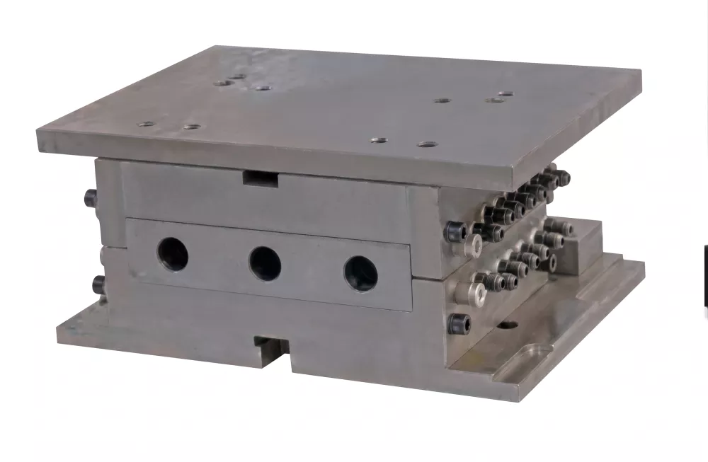
Fig 1 — Precision IBM injection mold: the foundation of consistent bottle quality and neck-finish accuracy
1. Why Mold Selection Determines Product Quality
Every quality attribute of an IBM bottle can be traced to a mold design or condition: neck-finish thread accuracy comes from the injection mold neck ring inserts; wall thickness uniformity comes from core rod concentricity; surface gloss comes from cavity polish level; cycle time comes from cooling channel layout. Mold wear and mold design deficiencies account for an estimated 40–60% of all IBM quality problems on established production lines — making mold specification and maintenance the highest-leverage area for quality improvement.
Visit our IBM machine product pages to understand which mold configurations are compatible with each machine model before beginning mold specification.
2. Types of IBM Molds: Core Rod, Injection Mold, Blow Mold
Core Rod Assembly
The steel rod set that transfers the preform between stations and defines the bottle interior diameter. Core rods are the highest-wear component in the mold set and should always be ordered as spare sets. Rod diameter determines neck inner diameter; rod length determines maximum bottle height.
Injection Mold
Forms the preform and neck finish geometry under injection pressure. Consists of cavity plate, neck ring inserts (defining thread form), and a hot or cold runner system. The injection mold operates under the highest thermal and mechanical stress of all three mold components.
Blow Mold
Two-piece split mold defining the final bottle body shape, label panel geometry, and bottom profile. Lower operating pressure than the injection mold; can be manufactured from aluminium for faster cooling and lighter weight. Vent grooves (0.02–0.04 mm) are machined into parting faces to allow air escape during blowing.
3. Mold Material Options: P20, H13, S136 Steel Comparison
| Steel Grade | Hardness (HRC) | Best For | Life Expectancy | Relative Cost |
|---|---|---|---|---|
| P20 | 28–34 | Low-volume, prototype, opaque PP bottles | 200,000–400,000 shots | Low |
| H13 | 48–52 | High-volume PP/PE, standard pharmaceutical | 800,000–1,500,000 shots | Medium |
| S136 (420SS) | 50–54 | PVC, PET, transparent/optical-grade bottles | 1,000,000+ shots | High |
| Aluminium 7075 | Brinell 150 | Blow mold only, fast-cycling, prototype | 50,000–150,000 shots | Very Low |
4. Cavity Number Selection: Single vs Multi-Cavity
Cavity count selection follows a straightforward production arithmetic: divide your required hourly output by the machine hourly cycle count to get the minimum cavities per station required. Common cavity counts are 2, 4, 6, 8, and 12 — always standardised to ensure symmetric clamping force distribution.
Worked example:
- Target: 3,600 bottles/hour
- Machine: 15-second cycle = 240 cycles/hour
- Minimum cavities: 3,600 ÷ 240 = 15 → round up to 16 (not a standard) or specify 12-cavity and accept 2,880 output, or accept a faster cycle time with 12 cavities.
- Practical choice: 6-cavity mold at 13-second cycle = 6 × 277 = 1,662/hour × 2 shifts meets a 3,000/day target with capacity margin.
Higher cavity counts increase mold complexity, cost, and the risk of cavity-to-cavity variation. For pharmaceutical products, 4-cavity molds offer a manageable balance of output and quality control. Cosmetic and food products with higher volume tolerances may justify 8 or 12 cavities.
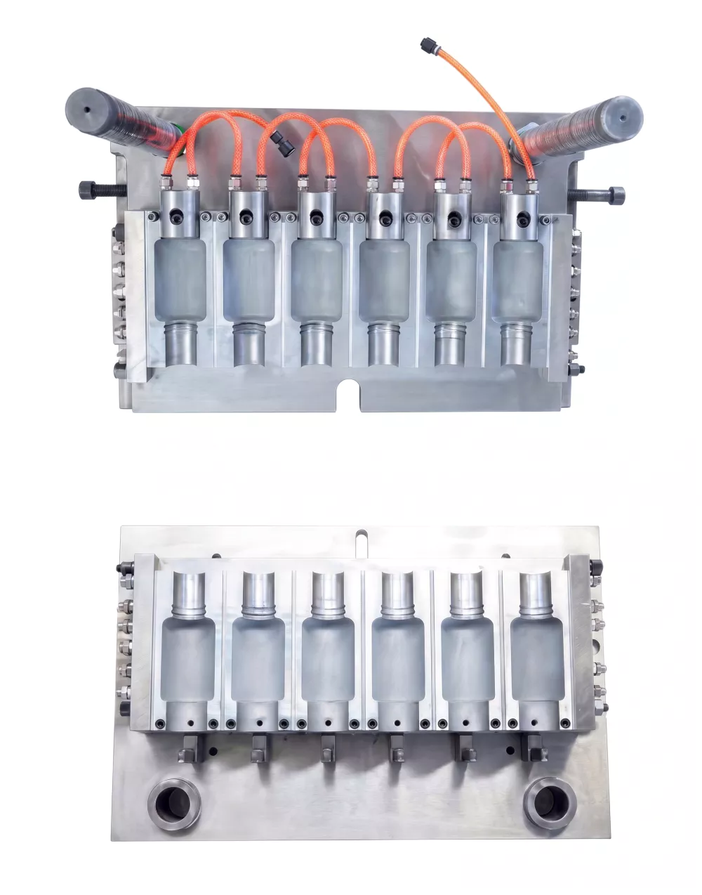
Fig 2 — IBM blow mold cavity layout: cavity count must match injection mold and machine specification
5. Matching Mold Dimensions to Machine Specifications
IBM molds must physically fit the machine platen size, tie rod spacing, and rotary table pitch. Critical dimensions to verify before mold design begins:
- Platen size (L × W) — mold base must fit within the machine daylight opening with minimum 20 mm clearance on all sides.
- Mold height (open/close stroke) — mold height must not exceed maximum daylight minus minimum clamp stroke.
- Core rod pitch circle diameter — all cavities must align with the machine core rod pitch circle exactly.
- Core rod diameter and length — must match mold core hole diameter to ±0.01 mm.
- Cooling circuit connections — inlet/outlet positions must clear the rotary table path; specify with machine layout drawing.
6. Mold Tolerance and Surface Finish Requirements
Dimensional tolerances for IBM molds are tighter than for most other plastic mold types because the preform and neck finish must be dimensionally accurate before any blowing occurs:
- Neck ring thread profile: ±0.05 mm on thread pitch diameter
- Core rod cavity clearance: 0.02–0.05 mm (preform wall = this clearance)
- Cavity roundness: ≤ 0.02 mm at any cross-section
- Parting face flatness: ≤ 0.01 mm/100 mm (prevent flash)
- Injection mold cavity polish: Ra 0.4 µm for transparent; Ra 0.8 µm for opaque
- Blow mold cavity finish: Ra 1.6–3.2 µm (grit blasted) for air venting and matte bottle surface
7. Cooling Channel Design and Its Impact on Cycle Time
Cooling typically accounts for 40–60% of total IBM cycle time. A well-designed cooling layout can reduce cycle time by 20–30% compared to a poorly cooled mold of the same geometry. Key design principles:
- Channel proximity: Position cooling bores 10–15 mm from cavity surface. Too close risks thermal shock; too far reduces cooling effectiveness.
- Channel diameter: 8–12 mm for standard molds; smaller diameters increase flow velocity and turbulence for better heat transfer but require higher pump pressure.
- Circuit balance: Use parallel circuits of equal length to balance flow rate. Series circuits build a significant temperature rise from inlet to outlet, causing uneven cooling.
- Core rod cooling: Internal core rod cooling channels must also be designed — the rod is in contact with hot melt on its outer surface for the full injection time.
8. Custom Mold Design vs Standard Mold: Cost Comparison
| Factor | Standard Mold | Custom Mold |
|---|---|---|
| Lead time | 2–6 weeks | 10–20 weeks |
| Cost premium | Baseline | +30–80% over standard |
| Design flexibility | Limited to catalogue sizes | Any bottle geometry |
| Modification risk | Low (pre-validated design) | Requires trial and correction |
| Best application | Common pharma/cosmetic bottle sizes | Branded packaging, novel neck geometry |
9. Mold Maintenance and Service Life Expectation
IBM mold life is a function of steel grade, cycle count, material processed, and maintenance quality. Key maintenance practices that extend mold life:
- Clean cavity surfaces with soft brass brushes — never steel wire or abrasive cloth on polished surfaces.
- Inspect and re-stone parting faces every 200,000 cycles to remove early flash buildup before it deepens.
- Flush cooling channels with descaling solution every 500,000 cycles to remove calcium deposits.
- Replace core rod sets at first sign of surface pitting or runout exceeding 0.05 mm.
- Store molds with cavities packed with VCI (vapour corrosion inhibitor) paper when not in use.
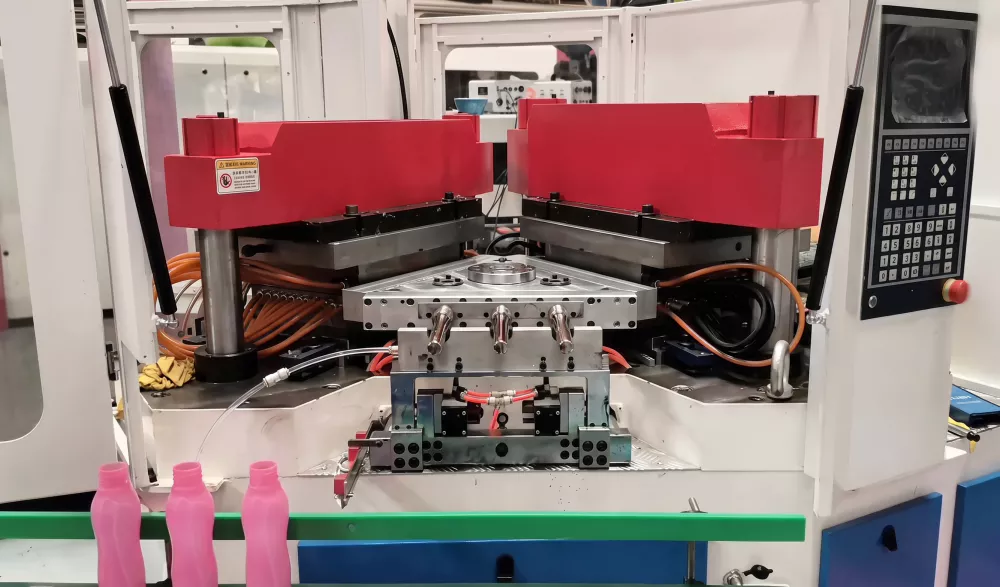
Fig 3 — Mold maintenance and timely replacement of worn components keeps IBM output quality consistent
10. How to Work with a Mold Supplier Effectively
Mold procurement is a collaborative engineering process, not a catalogue transaction. To get the best outcome:
- Provide machine drawings: Platen size, tie rod spacing, core rod pitch circle, and connection positions are all required by the mold maker before any design begins.
- Provide bottle drawing with tolerances: A full 2D drawing with GD&T callouts for the neck finish is the minimum specification. A 3D CAD file saves design time and reduces errors.
- Specify closure: Provide the actual closure that will be used, so the mold maker can design the neck ring inserts to the correct fit class.
- Request T1 samples: First-off mold trial samples should be measured and approved against drawing before series production.
- Clarify spare parts policy: Ensure spare core rods and neck ring inserts are included in the initial order — lead times for re-orders can be 4–8 weeks.
11. Frequently Asked Questions
What steel grade is best for IBM injection molds?
H13 hot-work tool steel is the most common choice for IBM injection molds running PP and PE, offering a good balance of hardness (48–52 HRC) and thermal fatigue resistance. S136 stainless is preferred for PVC or optical-clarity applications.
How many cavities should I choose for an IBM mold?
Cavity count should match your target output rate divided by machine cycles per hour. Always use standard even-number cavity counts to ensure symmetric clamping force distribution.
What is the difference between IBM injection mold and blow mold?
The injection mold forms the preform and critical neck finish under injection pressure. The blow mold defines the final bottle body shape. Both must match cavity count and pitch on the same machine.
How long does an IBM mold typically last?
A P20 mold produces approximately 300,000–500,000 shots before measurable wear. An H13 mold hardened to 50 HRC can reach 1,000,000+ shots with proper maintenance.
What surface finish should IBM mold cavities have?
Injection mold cavity finish should be Ra 0.4–0.8 µm for transparent containers and Ra 0.8–1.6 µm for opaque pharmaceutical bottles. Blow mold cavities are typically grit-blasted to Ra 1.6–3.2 µm.
How important is mold cooling channel design?
Cooling channel design directly controls cycle time and wall uniformity. Channels should be 10–15 mm from the cavity surface with balanced parallel circuits. Poor cooling is one of the top three causes of cycle time loss on IBM machines.
Should I buy a custom mold or a standard mold?
Standard molds offer lower cost and faster delivery for common bottle sizes. Custom molds are required for unique shapes or specialty neck finishes and typically cost 30–60% more with 8–14 weeks longer delivery.
Can I use molds from a different IBM machine model?
Not typically. Mold dimensions, core rod diameter, and station pitch are machine-specific. Always verify compatibility with the specific machine model before ordering. Cross-brand compatibility is rare without adapter plates.
12. Conclusion
Selecting the right IBM mold is a multi-variable engineering decision that determines production quality, cycle efficiency, and tooling economics for the full production life of your line. Specify steel grade to match your volume target, match cavity count to output requirements, design cooling to minimise cycle time, and work collaboratively with your mold supplier from the machine drawing stage onwards.
Our engineering team can review mold specifications before ordering and advise on compatibility with our machine range. Contact us or explore our IBM machine catalogue for machine-mold compatibility data.