Understanding exactly how an injection blow molding machine transforms raw plastic pellets into perfectly formed bottles is essential for anyone evaluating equipment, troubleshooting production issues, or optimising an existing line. This guide breaks the entire IBM process into clear, sequential steps — from material preparation through ejection — and explains the engineering behind each stage so you can make informed decisions about equipment, parameters, and molds.
Whether you manufacture pharmaceutical vials, cosmetic jars, or food-grade containers, the fundamental IBM workflow remains the same. Master it, and you gain the insight to raise output quality, reduce scrap, and optimise cycle times on any machine you operate.
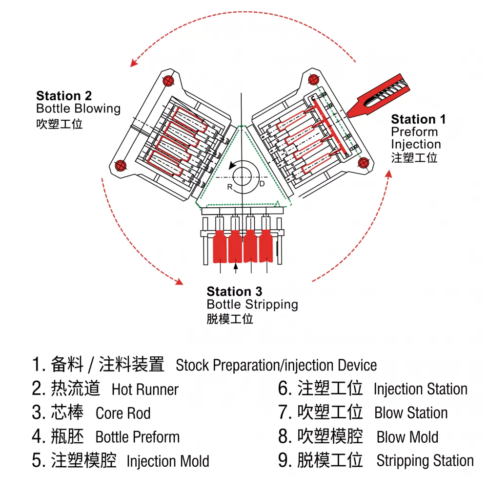
Fig 1 — Full IBM process cycle from injection station to ejection station
1. Why Understanding the IBM Process Matters for Buyers
Injection blow molding machines represent a significant capital investment. Buyers who understand the mechanics can specify the right clamping tonnage, cavity count, and auxiliary equipment from the start — preventing costly mismatches between machine capability and product requirements. Engineers who know each process stage can diagnose defects at their root cause rather than guessing. And operations managers who understand cycle-time drivers can set realistic production targets and negotiate maintenance contracts intelligently.
Visit our IBM machine product range to see how different model sizes align with different production volumes and bottle geometries.
2. Overview of the Injection Blow Molding Process
The IBM process is a three- or four-station rotary (or linear) operation in which a steel core rod acts as the central transfer mechanism. Molten plastic is first moulded around the rod, the rod then rotates or indexes to a blow station where compressed air inflates the bottle, and the finished container is stripped from the rod at the ejection station. On four-station machines a conditioning station between injection and blow allows fine temperature adjustment of the preform.
| Station | Action | Key Variable |
|---|---|---|
| Injection | Form parison around core rod | Melt temperature, injection pressure |
| Conditioning (optional) | Equilibrate preform temperature | Heater band settings |
| Blow | Inflate preform to final shape | Blow pressure, blow time |
| Ejection | Strip finished bottle from rod | Stripper plate timing |
3. Step 1 — Material Preparation and Plasticising
Before any plastic enters the machine barrel, raw resin pellets must be dried to specified moisture levels. PP typically requires 2–4 hours at 80 °C; PE needs minimal drying; PET must reach below 50 ppm moisture — usually 4 hours at 160 °C in a desiccant dryer. Inadequate drying causes hydrolysis, surface splay, and mechanical weakness in the finished bottle.
Inside the plasticising barrel, a reciprocating screw rotates and advances, generating frictional and conductive heat to melt the pellets. The screw compresses the melt, vents any residual moisture, and accumulates a precise shot volume in front of the screw tip. Backpressure setting (commonly 5–15 bar) controls melt density and homogeneity.
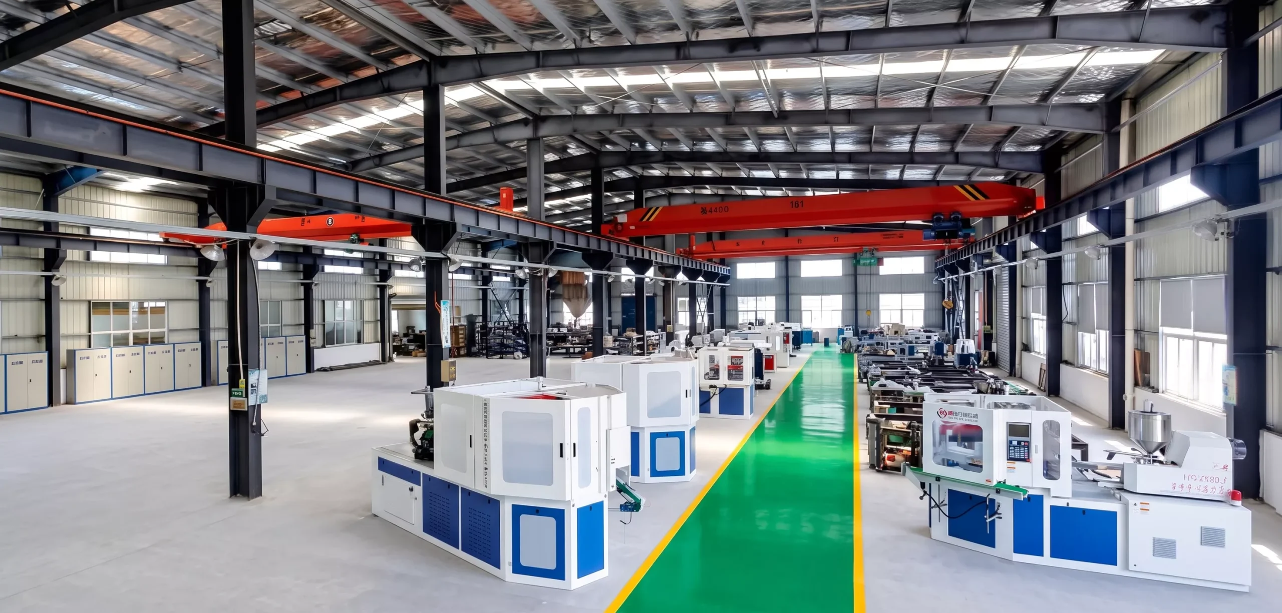
Fig 2 — Modern IBM machine factory floor with multi-cavity production lines
4. Step 2 — Injection Moulding of the Preform
With the injection mold closed around the core rod, the plasticising unit shoots the metered melt through a hot runner or sprue into the mold cavity. Injection pressure (typically 800–1,800 bar at the nozzle) packs the cavity completely and compensates for material shrinkage during initial solidification. The mold is water-cooled to harden the outer skin of the preform while the core rod maintains the inner dimension.
Critically, the neck finish — threads, sealing surface, and neck diameter — is fully formed at this injection stage and dimensionally locked in. This is one of IBM key advantages over extrusion blow molding: the neck finish needs no trimming and is consistent to very tight tolerances.
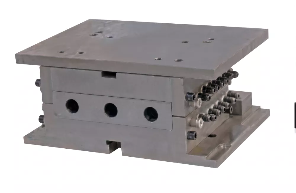
Fig 3 — Injection mold assembly with core rod: the foundation of dimensional precision
5. Step 3 — Transfer to the Blow Station
Once the preform skin has solidified sufficiently, the injection mold opens and the rotary table (or linear shuttle) indexes the core rod — with the preform still on it — to the blow station. This transfer happens with the preform at a carefully managed temperature: hot enough to be blown without re-heating, yet cool enough to retain the neck finish geometry. On three-station machines this balance is achieved by precise mold-cooling timing. Four-station machines add a conditioning station where heater bands can raise or equalise preform temperature zone by zone.
Rotary machines typically index through 120° per station (three stations) or 90° (four stations). The indexing speed must be fast enough to maintain short cycle times without mechanical shock to the preform.
6. Step 4 — Blow Moulding and Bottle Forming
At the blow station the blow mold closes around the preform-on-rod assembly. Compressed air — at 6–10 bar for PP/PE, up to 15 bar for PET — is introduced through the hollow core rod. The preform inflates radially outward until it contacts the blow mold cavity walls and takes the precise shape of the finished bottle body.
Blow time is held for 2–8 seconds while the mold cooling channels chill the bottle walls to a stable temperature. Blow pressure must be maintained throughout this hold time to prevent elastic recovery (spring-back) that would distort the final shape. At the end of blow time, the air is vented, the blow mold opens, and the table indexes again.
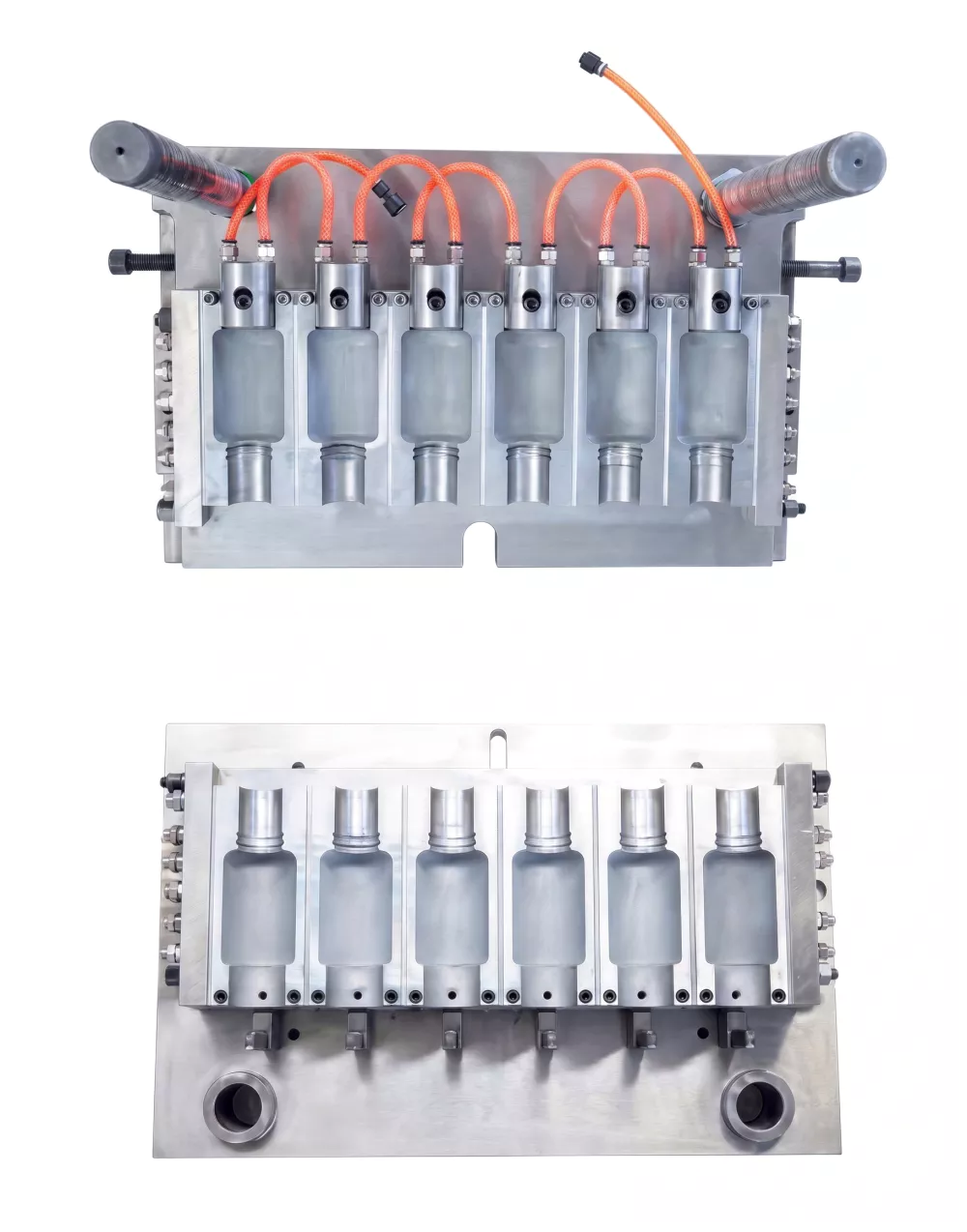
Fig 4 — IBM blow mold halves with cooling channels for rapid bottle solidification
7. Step 5 — Ejection and Product Cooling
At the ejection station a stripper plate or cam-driven mechanism pushes the solidified bottle off the core rod. The bottle falls into a collection chute or onto a conveyor. On continuous rotary machines all three (or four) stations operate simultaneously — while one bottle is being ejected, the next preform is being injection moulded and another is being blown. This simultaneity is what makes IBM highly productive relative to its machine footprint.
Some lines include in-line leak testing, vision inspection, or direct labelling after ejection to compress total cycle time from moulding through quality control.
8. Key Components Involved at Each Stage
Plasticising Barrel & Screw
L/D ratio typically 20:1 to 24:1. General-purpose screw geometry for PP/PE; barrier screws for PET. Electrically heated barrel zones (3–5 zones) with PID temperature control.
Core Rod Assembly
Hardened steel rods (H13 or S136) with internal cooling channel. Rod diameter sets bottle neck inner diameter. Surface finish Ra 0.4 µm or better for easy release.
Injection Mold
2–12 cavities machined from P20 or H13 steel. Hot runner preferred for multi-cavity to eliminate cold sprue. Neck ring inserts define thread geometry with ±0.05 mm tolerance.
Blow Mold
Split two-piece mold, often aluminium for faster cooling or P20 steel for longer life. Vent grooves (0.02–0.04 mm) prevent air trapping. Cavity surface texture transferred directly to bottle.
Blowing Nozzle
Seats against the core rod head to deliver compressed air into the hollow preform. Must withstand cyclic pressure fatigue; hardened stainless steel recommended.
Hydraulic / Servo Drive
Drives mold open/close, injection unit advance, and table indexing. Servo-hydraulic systems reduce energy consumption 20–40% versus fixed-displacement pumps.
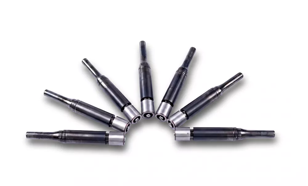
Fig 5 — Precision blowing nozzle: the component that delivers forming air into the preform
9. Common Process Parameters and How to Adjust Them
| Parameter | Typical Range (PP) | Effect of Increasing | Effect of Decreasing |
|---|---|---|---|
| Melt Temperature | 200–240 °C | Better flow, lower stress; risk of degradation | Short shots, high stress, poor surface |
| Injection Pressure | 800–1,400 bar | Fuller cavity, less sink; risk of flash | Short shot, sink marks |
| Blow Pressure | 6–10 bar | Better detail replication; risk of mold wear | Incomplete inflation, soft corners |
| Blow Time | 2–6 s | Better cooling, less spring-back; longer cycle | Deformation on ejection |
| Mold Temperature | 10–30 °C | Glossier surface; slower cycle | Faster cycle; risk of stress whitening |
| Cycle Time | 8–20 s | — | Higher output; risk of defects |
10. Advantages of the IBM Process vs Other Methods
IBM distinctive process architecture confers several competitive advantages:
- No flash or trimming required — the bottle is formed to net shape, saving secondary operations and material waste.
- Tight neck-finish tolerances — ±0.1 mm or better, critical for pharmaceutical closure integrity.
- Consistent wall thickness — injection around the core rod ensures controlled parison geometry before blowing.
- High surface quality — the smooth injection mold surface is reproduced on the bottle body.
- Suitable for complex neck geometries — roll-on closures, child-resistant caps, and tamper-evident bands are all achievable.
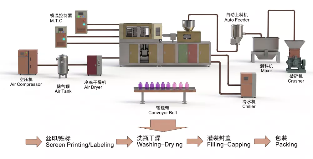
Fig 6 — Complete IBM production line: machine, dryer, chiller, and downstream handling
11. Frequently Asked Questions
What is the basic principle of injection blow molding?
The IBM process first injects molten plastic around a steel core rod to form a preform, then transfers the preform to a blow station where pressurised air expands it into the final bottle shape inside a blow mold.
How long does one IBM cycle take?
A typical cycle for small pharmaceutical bottles (10–60 ml) runs 8–18 seconds, depending on wall thickness, material, and cooling efficiency.
What materials can be processed on an IBM machine?
IBM machines process PP, PE, PET, PVC, and PETG. PP and PE are most common for pharmaceutical and cosmetic bottles.
What is the difference between the injection station and the blow station?
The injection station forms the parison by injecting molten resin into a closed mold around the core rod. The blow station uses compressed air through the core rod to expand the preform against the blow mold walls.
Can an IBM machine run multiple cavities simultaneously?
Yes. Most IBM machines operate with 2, 4, 6, or more cavities per station, allowing simultaneous production of multiple bottles per cycle.
Why is cooling important in the IBM process?
Adequate cooling solidifies the bottle walls before ejection, preventing deformation and ensuring dimensional accuracy. Both the core rod and blow mold incorporate cooling channels.
12. Conclusion
The injection blow molding process is an elegantly integrated sequence where every station depends on the precision of the one before it. Mastering the relationship between material preparation, preform geometry, blow pressure, and cooling yields bottles that consistently meet tight dimensional and quality standards.
Ready to put this knowledge into practice? Explore our full range of injection blow molding machines or contact our engineering team to discuss your specific bottle requirements and production volume.