
How to Improve Production Efficiency and Reduce Cycle Time on an ISBM Machine?
Every second saved from the ISBM machine cycle time compounds into significant production gains over a shift, a week, a year. Reducing cycle time from 16 seconds to 13 seconds — a seemingly modest 3-second improvement — increases hourly output by 23% on a 2-cavity machine: from 450 to 554 bottles per hour. Over a three-shift operation, this translates to over 1,000 additional bottles per day from the same machine, the same operator, and the same utilities.
But cycle time reduction is not simply a matter of turning down a timer setting. ISBM cycle time is constrained by several sequential and parallel physical processes — injection cooling, conditioning dwell, stretch-blow, and bottle cooling — each of which has a physical minimum that cannot be bypassed without producing defects. The challenge is to identify where current cycle time is genuinely conservative and where it is running at or near the physical minimum, then apply targeted optimisation strategies to each bottleneck.
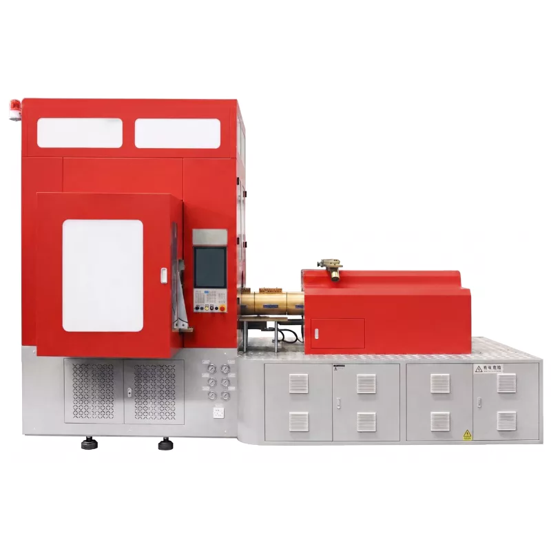
Understanding the ISBM Cycle Time Anatomy
The ISBM cycle time is the time elapsed between successive table indexing movements. During this time, all four stations are active simultaneously — so the cycle time is dictated by the slowest station, not by any single step in isolation. Before attempting to reduce cycle time, it is essential to identify which station is the current bottleneck.
| Station | Time Contribution Elements | Typical Duration (100–500ml PET) | Optimisation Lever |
|---|---|---|---|
| Injection | Mold close, injection, hold, cooling in mold, mold open | 8–14 s | Cooling time; injection speed; mold water temp |
| Conditioning | Preform temperature adjustment dwell time | = Table indexing time (same as cycle) | Heater power; preform entry temperature |
| Stretch-Blow | Mold close, rod stroke, pre-blow, main blow, hold, exhaust, mold open | 3–6 s | Blow mold cooling; blow hold time; exhaust time |
| Ejection | Core rod withdrawal, stripper, bottle drop, core rod return | 1–2 s | Usually not the bottleneck |
| Table indexing | Rotation between stations | 0,5–1,5 giây | Drive speed; mechanical condition |
Strategy 1 — Reduce Injection Mold Cooling Time
The injection station is almost always the cycle time bottleneck, because the preform must cool sufficiently in the mold to retain its shape on ejection from the core rod — and injection cooling depends directly on the heat flow from the molten preform through the mold steel to the chilled water circuit. Shortening cooling time requires improving heat transfer rate:
Reducing chilled water temperature from 12°C to 6°C increases the temperature differential and heat extraction rate. Check for condensation on the mold exterior — if the ambient dew point is above the water temperature, condensation can cause water contamination of the preform interior. Insulation of water circuits may be needed.
Turbulent flow in cooling channels extracts heat faster than laminar flow. Verify that flow rates meet the minimum turbulence (Reynolds number) threshold for each cooling circuit. Adding a flow booster pump can increase Reynolds number without changing water temperature.
Calcium and mineral scale deposits inside cooling channels act as thermal insulators, significantly reducing heat transfer. Measure inlet vs outlet water temperature — a large differential across the mold indicates good heat exchange; a small differential indicates scale blockage. Regular descaling (chemical or ultrasonic) maintains cooling efficiency.
The core rod contacts the inner surface of the preform directly. Internal core rod cooling (water flowing through the rod centre) is a significant contributor to overall cooling. Ensure core rod cooling water temperature and flow are at their specified values; worn or corroded rod cooling holes reduce cooling dramatically.
Strategy 2 — Optimise Conditioning Station Efficiency
In one-step ISBM, the conditioning station uses the preform’s residual injection heat as a starting point. The goal is to profile the preform temperature from its as-ejected state to the blow window temperature within one cycle time. Strategies to improve conditioning efficiency:
- Reduce injection mold cooling to minimum acceptable: The less the preform is cooled in the injection mold (while still being stable on ejection), the less the conditioning station must add back. Preforms ejecting at 60°C (body) require less conditioning than those ejecting at 40°C.
- Zone the conditioning heaters: Independent control of upper, mid, and lower conditioning zones allows the preform to reach uniform blow temperature faster by compensating for the natural temperature gradient that develops during injection cooling.
- Check heater element output: Aging IR heater elements lose output over time. Measure actual surface temperature of the conditioning zone heater elements; replace elements showing more than 15% output reduction versus specification.
- Verify neck cooling is not over-cooling the body: In machines with active neck cooling, over-cooling can create cold zones in the upper body that reduce conditioning efficiency and require longer dwell time to overcome.
Strategy 3 — Shorten Blow Station Cycle Time
The blow station has several time elements that can often be reduced without sacrificing bottle quality:
| Element | Reduction Strategy | Risk to Monitor |
|---|---|---|
| Blow hold time | Reduce hold time by 0.1s increments; inspect each sample for bottle deformation (oval cross-section, shrinkage from mold wall) | Bottle distortion on ejection if reduced too far |
| Exhaust / blow pressure release | Ensure exhaust valve is opening fully — worn exhaust valves slow pressure release, extending effective blow time | Residual pressure causing bottle lift on mold open if exhaust insufficient |
| Blow mold cooling water temperature | Lower blow mold water temp to improve bottle cooling rate — allows shorter hold time | Condensation in high-humidity environments |
| Mold open/close speed | On servo or proportional valve machines, increase traverse speed to maximum machine specification — mechanical limits are conservative for new machines | Mold impact damage if speed exceeds mechanical limit; verify deceleration is adequate |
Strategy 4 — Reduce Unplanned Downtime (OEE Improvement)
Overall Equipment Effectiveness (OEE) — the product of Availability, Performance, and Quality rates — is the most meaningful production efficiency metric for an ISBM machine. Even a machine running at a fast cycle time delivers poor overall efficiency if it is frequently stopped for faults, changeovers, or quality holds. Improving OEE through reduced downtime often delivers more output gain than squeezing additional cycle time:
Implement a rigorous preventive maintenance schedule (daily, weekly, monthly). Keep a fault log and analyse the top 3 most frequent fault codes — address root causes rather than resetting alarms. Maintain a spare parts inventory for the most frequently replaced items (heater elements, stretch rod tips, seal kits).
Track actual bottles produced per shift versus theoretical maximum at set cycle time. Calculate actual OEE Performance rate. If performance is below 90%, investigate micro-stops (brief machine pauses that don’t appear in the fault log but accumulate significant dead time).
Every rejected bottle represents a full cycle time invested with zero output. Track reject reason codes at each production run. High scrap rates are often caused by process drift (heater aging, water temperature drift, resin lot variability) — address root causes with SPC monitoring of critical parameters.
Strategy 5 — Energy Efficiency Alongside Cycle Time Optimisation
Reducing cycle time while simultaneously reducing energy consumption per bottle requires attention to process efficiency rather than simply increasing machine speed. These measures reduce kWh per 1,000 bottles without necessarily changing cycle time:
- Use variable-frequency drives (VFDs) on hydraulic pump motors — significant energy savings during low-load phases of the cycle
- Recover blow exhaust air: on-machine air recovery systems reuse exhausted high-pressure air (20–25 bar) for pre-blow (4–6 bar), reducing booster compressor demand by 15–25%
- Insulate barrel and hot runner heating zones — reduces heat loss to the factory environment and stabilises barrel temperature control
- Optimise heater on/off cycles in conditioning station — only heat during active conditioning; reduce power during machine standby
- Monitor and address compressed air leaks — even small leaks at fittings represent significant booster compressor energy waste in HP air circuits
The HGY-V4-EV models in our machine range incorporate these energy recovery features as standard. View the EV series specifications for energy consumption data at rated output.
Quick Reference — Cycle Time Reduction Checklist
| Hoạt động | Potential Saving | Difficulty |
|---|---|---|
| Lower injection mold water temperature by 3–5°C | 0,5–1,5 giây | Thấp |
| Descale cooling channels (if not done in past 6 months) | 0,5–2,0 giây | Low-Medium |
| Reduce injection mold cooling time by 1–2s trial (inspect carefully) | 1.0–2.0 s | Trung bình |
| Reduce blow hold time by 0.1–0.3s trial (inspect carefully) | 0.1–0.5 s | Thấp |
| Replace aging conditioning heater elements | 0.5–1.0 s (from faster temperature reach) | Thấp |
| Check and restore exhaust valve to full-open operation | 0.2–0.5 s | Thấp |
| Implement OEE tracking to identify and reduce micro-stops | 5–15% output increase (availability gain) | Trung bình |
For a systematic production efficiency review for your specific machine and bottle programme, contact our technical support team. We offer remote OEE analysis and on-site efficiency audits for all ISBM machines we supply.
Câu hỏi thường gặp
What is the minimum achievable cycle time for a standard 500ml PET bottle on a one-step ISBM machine?
Will reducing cycle time affect bottle quality or mechanical properties?
How does ambient temperature affect ISBM machine cycle time?
Want a Cycle Time and OEE Improvement Audit for Your ISBM Machine?
Share your current cycle time, bottle specification, machine model, and average OEE — we will identify the specific opportunities for improvement in your operation.
Request an Efficiency Audit
View High-Efficiency Machine Range