
ISBM Machine Mold Design: Kernregels voor Preform- en Blow Mold Engineering
The mold tooling set is the most capital-intensive and process-critical component of any ISBM machine installation. A well-designed mold produces consistent, high-quality bottles efficiently for millions of cycles; a poorly designed mold generates chronic quality defects, excessive scrap, unplanned downtime, and difficult-to-diagnose process instability. Unlike machine parameters — which can be adjusted — a mold design error is baked in at manufacture and can only be corrected by remachining or replacing the tool.
This guide covers the engineering rules that govern ISBM preform mold and blow mold design, written for packaging engineers specifying new tooling, mold designers working on ISBM-specific projects, and production managers evaluating why their current tooling is underperforming. Understanding these rules also helps buyers ask better questions when ordering tooling from a supplier.
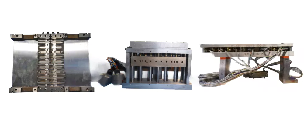
The Two-Mold System: How They Work Together
Every one-step ISBM tooling set comprises two fundamentally different molds that must be designed as an integrated system:
Produces the preform — a test-tube-shaped intermediate with all final neck dimensions already formed. The preform body is thick-walled and short: this is the material reservoir that will be stretched and blown into the final bottle. The injection mold must deliver precise gate geometry, uniform cavity fill, and sufficient cooling to allow ejection within the cycle time without preform distortion.
Defines the final bottle geometry. The heated preform, held on the core rod, is positioned inside the blow mold cavity; the stretch rod and compressed air expand it outward until all surfaces contact the mold wall. The blow mold must deliver: accurate cavity geometry matching the bottle drawing, efficient cooling to set the bottle within the blow hold time, and precise venting to prevent air trapping that causes incomplete panel formation.
The critical linkage between the two molds is the stretch ratio relationship: the preform body dimensions (length and diameter) must produce the target axial stretch ratio (ASR) and hoop stretch ratio (HSR) when blown into the bottle cavity. This relationship must be calculated at the design stage — it cannot be corrected later by adjusting machine parameters alone.
Preform Mold Design Rules
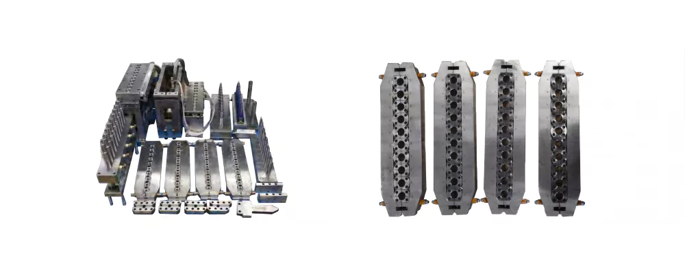
Rule 1 — Gate Design
The gate is the injection point at the base of the preform cavity. In ISBM, the gate zone is also the point where the stretch rod tip contacts and pushes through during the blow station — making gate design doubly critical.
- Gate type: Hot tip gate (valve gate or open tip) is standard. Sprue gate creates excessive gate vestige that the stretch rod must push through, causing gate marks. Cold runner is almost never used in ISBM.
- Gate diameter: Typically 0.8–1.4mm for PET; larger for PP (higher viscosity). Too small = shear degradation, gate freeze, short shots. Too large = gate blush, slow freeze, long cooling required.
- Gate land length: Minimum practical length — long lands increase shear heating and gate vestige height, which creates stretch rod interference.
- Gate vestige height: Must be specified to be flush or below the preform base surface — any protrusion above the preform base plane will be contacted by the stretch rod tip and cause gate puncture or rod deflection marks.
Rule 2 — Preform Wall Thickness Distribution
The preform wall thickness profile directly controls the final bottle wall thickness distribution. In ISBM, the relationship is approximately inverse — where the preform is thicker, the bottle wall will be thinner (more material has been stretched away). Design principles:
| Preform Zone | Design Consideration | Common Error |
|---|---|---|
| Neck (no stretch) | Wall set to final bottle neck wall — not stretched | Over-thick neck causing slow cooling; CRC torque failure |
| Shoulder transition | Gradual taper to avoid abrupt wall change; controls shoulder thickness | Abrupt transition creates stress concentration → thin shoulder in bottle |
| Body (main stretch zone) | Typically 3–5mm for PET; uniform or slightly tapered (thicker at base) | Uniform body when bottle requires heavier base — leads to thin base in bottle |
| Base / gate zone | Heavier wall than body; forms the bottle base (lower stretch here) | Too thin base causes base puncture during stretch; too heavy causes extended cooling time |
Rule 3 — Neck Finish Geometry
The neck thread and support ledge are formed to final dimensions in the injection mold cavity and never deformed again — this is ISBM’s key precision advantage. Neck design rules:
- Use industry-standard neck finishes (GCMI, PCO, ROPP, etc.) wherever possible to ensure closure supplier compatibility and documented dimensional tolerances
- Neck cavity requires the tightest machining tolerances in the tool — typically ±0.02mm on thread diameter and pitch
- Support ledge flatness and squareness to the neck axis are critical for induction heat seal liner seating and tamper-evident band function
- Neck cavity must be cooled independently — neck cooling controls crystallinity in the neck zone and affects CRC torque consistency
Rule 4 — Cooling Channel Design
Cooling time is the primary driver of injection station cycle time. Efficient cooling channel design can reduce cycle time by 2–4 seconds versus a poorly cooled mold of the same cavity geometry:
- Channel diameter: minimum 6mm (8mm preferred) for adequate flow rate and turbulent regime
- Channel-to-cavity distance: 8–12mm is the practical optimum — too close risks breakthrough; too far reduces heat transfer rate
- Cooling channels must surround the cavity uniformly — dead zones at corners or base create hot spots and uneven cooling
- Core rod internal cooling is equally important and is often the limiting factor — verify core rod cooling water temperature and flow rate specification
- Conformal cooling (3D-printed inserts) offers significant cycle time reduction for complex cavity geometries but at higher tooling cost
Blow Mold Design Rules
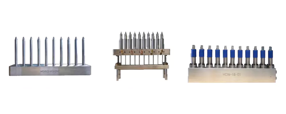
Rule 5 — Draft Angles
All surfaces parallel to the mold opening direction must have sufficient draft to allow bottle release. In blow molds, draft angles are especially critical because the bottle wall contacts the mold under high air pressure and must release cleanly when the mold opens:
- Minimum draft: 1° for smooth surfaces; 2–3° for textured or embossed surfaces
- Recessed panel designs (concave panels common in PET water bottles) require careful draft analysis — the panel base must be drafted even if the surrounding surface is vertical
- Embossed lettering or logos: each letter element must be drafted; minimum 3° on embossed features
- Under-drafted features cause bottle sticking, surface marks from forced ejection, and mold wear over time
Rule 6 — Parting Line Placement
The blow mold parting line — where the two mold halves meet — leaves a faint seam line on the bottle body. For standard bottles this is functionally insignificant but aesthetically important in premium cosmetic and pharmaceutical packaging. Design rules:
- Place the parting line along the narrowest cross-section of the bottle, or at a natural geometry edge (e.g. the bottom of a panel groove) to minimise visual impact
- Avoid placing parting lines through critical decoration areas (label panel centres, embossed brand marks)
- Parting line flash is controlled by mold clamping force and mold face flatness — verify face flatness is within 0.01mm after mold manufacture
- For round bottles, the parting line can be placed at any diametrically opposite point; for oval or asymmetric bottles, parting line placement must be specified in the mold drawing
Rule 7 — Venting
As the preform expands inside the blow mold, the air trapped between the preform outer surface and the mold cavity wall must escape. If it cannot escape fast enough, it compresses ahead of the expanding preform and prevents full contact with the mold surface — producing flat spots, incomplete shoulder radius, and poor surface finish. Venting rules:
- Vent slots: 0.01–0.03mm deep, 3–5mm wide, machined at the parting line and at panel bases, shoulder radii, and base edges
- Vent depth must be carefully controlled — too deep allows material extrusion into the vent creating flash lines on the bottle
- Sintered steel inserts at difficult-to-vent areas (enclosed pockets, deep base profiles) allow air to permeate through the insert without creating a vent mark on the bottle surface
- Blocked vents are a common cause of recurring incomplete panel fill defects — vents must be cleaned regularly as part of the mold maintenance schedule
Rule 8 — Blow Mold Cooling
Blow mold cooling sets the minimum blow hold time — how long the bottle must remain under pressure against the cooled mold surface to dimensionally stabilise before the mold opens. Cooling design rules:
- Water temperature: 8–15°C for PET; higher for PP (too cold causes PP to crystallise prematurely)
- Cooling channels must be placed close to the bottle base — the base accumulates the most heat because it is the last area to receive the stretch-blow deformation
- Aluminium alloy blow molds (7075 series) conduct heat 4× faster than steel, enabling shorter blow hold times — preferred for high-speed applications despite lower wear resistance
- Steel blow molds (P20, H13) offer better wear resistance and longer polishing life — preferred for high-cavitation production and abrasive materials
Mold Steel Selection Guide
| Component | Recommended Material | Reason |
|---|---|---|
| Preform cavity inserts | Stainless steel (420SS or S136) or beryllium copper | Corrosion resistance from condensation; high polish for clarity; beryllium copper for high-conductivity cooling |
| Neck cavity splits | Tool steel (H13 or similar) hardened to 48–52 HRC | Thread form must resist wear over millions of injection cycles |
| Core rod | Tool steel or stainless; hard chrome plated | Chrome plating reduces friction on preform ejection; improves heat transfer to cooling water |
| Blow mold (standard) | Aluminium 7075-T6 (high speed) or P20 steel (standard) | Al7075 for fast cycle / low cost; P20 for longer run life and better surface durability |
| Blow mold base insert | Beryllium copper or hardened steel | Base receives highest heat load; beryllium copper improves local cooling rate significantly |
For all tooling enquiries for our ISBM machine range, our mold engineering team can review your bottle design and provide a tooling specification with preform design proposal. Submit your bottle drawing for a tooling assessment.
Veelgestelde vragen
How long does it take to manufacture a new ISBM mold set?
Can I use the same preform mold with different blow molds to make different bottle shapes?
What information does a mold supplier need to quote an ISBM mold set?
Need a Tooling Quote for Your ISBM Bottle Project?
Send us your bottle drawing or concept sketch, material, and required output — our mold engineering team will propose a preform design, tooling specification, and indicative quote.